Year, Size, Model Identification
Every work day I receive calls from someone looking for parts to restore
or repair one of the many models of Penton and KTM motorcycles that were
sold from 1968 thru 1982. I am pretty good at knowing what some of the
parts many people are calling about, especially if I know what year,
model, and size of motor the bike is. It
saves a lot of time if the caller knows this information before calling.
It also helps if the caller has a part number to identify exactly what
part that they are looking for.
To identify what year, size, and model bike you have,
write down the serial number off of the frame (stamped on the steering
head). On the KTM motors, write down the number stamped on the ignition
side of the center case (right under the cylinder fins).
Penton/ KTM Frame Identification


1974 frame
1976 MC-5 1978 GS-6 frame
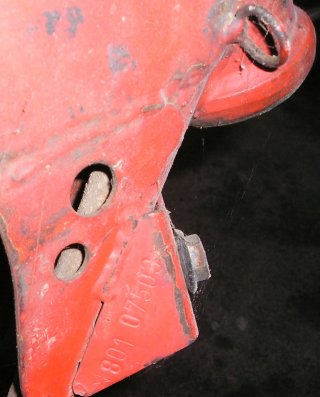
The frame serial numbers contain a date code that
identifies what month and year the bike was built. These number are
stamped on or around by the steering head. In most cases (from
1972+) the first three numbers are the date code. The first number is
the year, the next two are the month (eg. 403 = March of 1974).
KTM Motor Identification

1976- 400 1982- 420 1988- 350
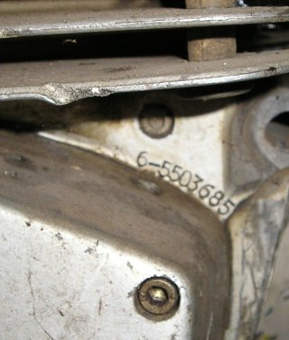
The KTM motor serial number
also contain a code that identifies what year and what size the motor
is. On the 1972-80 motors these numbers can be found on the ignition
side - just below the cylinder fins. On 1978+ motors the number can be
found on the clutch side - on the bottom front. The first three numbers
are the code. The first number is the year, the next two are the code
for the motor size. The following is a list of the different codes used
from 1972 thru 2003:
51 = 125 1976-81 52 = 175 363 = 50cc
450= 50 SXR/ S5-E/T/GS 1997 490 = 80cc LC 1986
510 = 125 1976-81 520 = 175 503 = 125 1998-2001
54
= 250 1973-80 55 = 400
523 = 200cc 1998-2001
540 = 250 1973-80
550 = 400
500 = 125/II RV or II LC 501 = 125 MX/MXC/GS (LC)
502 = 125 LC 1987-1992
503= 125 LC 1998
523 = 200 LC 1998
541 = 250II GS(RV) 542 = 250 MC 565-30-005 = 500 LC 1990
543 = 250 LC 546 = 250/300/380 1996 547= 250/300/380 2000
555 = 350 LC 1986 565-30-205 = 540 LC 1990
560 = 420 1979-84 561 = 350 1980 580-30-005 = 500 (90mm) 1988
562 = 390 GS 1980 563 = 495 1980-83 580-30-605 = 600 (95mm) 1988
583= 400/620SX,EGS LC4 1996 584= 400/620 LC4 1997 584= 625 LC4 2003
590 = 400/520 LC4 2000
590 = 250/450/525 2003 770 = 250 LC4 SX-F 2005
LC = Liquid Cooled
LC4= Liquid Cooled 4 stroke GS = Enduro
RV = Reed Valve
MC = Motocross
SX= Super Cross
These codes are not only used to identify models on the
motor cases, but are also used in the parts books to identity parts for
these motors. In most cases, the first two or three numbers in a part
number identify what size motor it goes to.
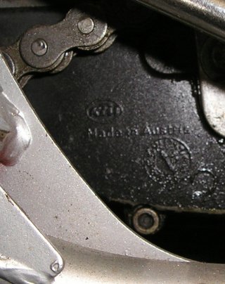 There is a date code cast into every motor case around the drive
sprocket area towards the lower rear part of the motor. It looks like a small clock with a triangular arrow in
the center. The arrow points to a number on the clock indicating the
month. There are two numbers under the arrow which indicate the year.
There is a date code cast into every motor case around the drive
sprocket area towards the lower rear part of the motor. It looks like a small clock with a triangular arrow in
the center. The arrow points to a number on the clock indicating the
month. There are two numbers under the arrow which indicate the year.
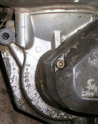
There are also part numbers cast into the outside of the center cases. The first two or three numbers are a way of identifying what size the motor is.
It is important for everyone to be able to identify what year and size bike that they have. Most used bikes have the original motors still in the frames, however I have run across situations where the motors have been replaced with a dissimilar year. (e.g.. a 1979 frame with a 1976 motor). Although many of the early KTM motor parts are the same and are interchangeable (1974 thru 1979) there are differences in some of the parts especially the clutches, push rods, and bearing plates.
Owners manuals are a must for anyone who has a Penton motorcycle. It not
only gives you step by step instructions on how to tear down the motor
and rebuild it, it also gives all of the specifications for the bike
along with recommended maintenance and adjustment of all of the
components on the bike. For anyone who has just obtained a Penton for
the first time, the owners manual is a must. The manual should be read
first before tearing into anything on the bike!
Owners manuals are available. Go to the
Repair Manuals - KTM page.
Parts lists are available showing every part on the bike and motors and
identify everything with a part number. The illustrations help in
determining if something is missing, what order the parts go in
assembly, and how many there should be. The part numbers help you to
obtain the exact part that you need.
For the 1972 thru 1973 they are sold by model size. For
1975 thru 1977 they are sold by model year and include the parts for the
125/175/250/400 in the same list. Go to the
Repair Manuals - KTM page.
Piston Specifications
When to Re-bore a Cylinder
Maximum allowable piston to cylinder clearance
125cc - .0055” to .006”
175cc - .006” to .007”
250cc - .006” to .007”
400cc - .006” to .007”
Specifications for Ring End Gaps
minimum maximum
125cc - .007 - .008 .015
175cc - .010 - .012 .018 - .020
Clearance Specs for Boring Cylinders
125cc - .0025” to .003”
175cc - .003” to .0035”
250cc - .0025” to .003”
400cc - .003” to .0035”
KTM Motor Tips
Do not remove the stop bolt for the kick starter, on the bottom of the motor, to drain the oil. Follow the directions in the owners manual to do oil changes. When doing an overhaul of the motor, remove the stop bolt after removing the kick starter shaft. Check the bolt for wear. If it is worn flat, replace it.
On the black motors, check for cracks around the hole in the case for the kick-start stop bolt. Cracks and breaks can be welded. ALL KTM MOTORS ARE MADE OF MAGNESIUM. Take it to a certified welder with experience. They use magnesium welding rods. Small cracks can be repaired with JB Weld or any high temp. epoxy to seal oil leaks.
On 250, 400, 420, and 495 motors, check and tighten any loose nuts and bolts after every race day. Pay attention to the motor mounting bolts on all big bore bikes. Loose bolts will allow the vibration of the motors to wear away the magnesium mounting areas.
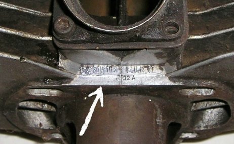
Casting mark under exhaust port
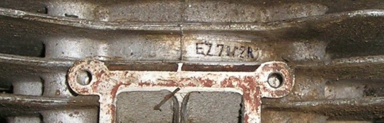
250 casting mark above intake
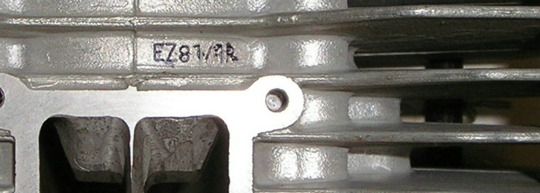
400 casting mark above intake
KTM Cylinder Re-sleeving
All KTM cylinders can be re-sleeved, however in some cases there are more than one style of sleeve for a size of cylinder - in particular the 250 and 400 cylinders.
The 250 cylinders could use a sleeve with a standard bore size of 71 or 72mm. Look for casting mark "ELKO EZ 71" or "ELKO EZ 72"
The 400 cylinders could use a sleeve with a standard bore size of 81 or 82mm. Look for casting mark "ELKO EZ 81" or "ELKO EZ 82"
Double check the casting marks on your cylinder (see above photos for locations) to determine what size cylinder that you have before calling to order a new sleeve.
The 1972-75 175 cylinders were throw-a-way cylinders that did not have replacement sleeves. The cylinder must be over-bored to install a sleeve.
Do not take your cylinder to just any shop for re-sleeving or boring. Make sure that they have the experience of working on vintage 2-stoke cylinders. Shops doing work on the new motors can screw up your cylinder because there is a difference in setting them up.
KTM Liquid Cooled Engines - clutch case covers
Almost all KTM engines are made of magnesium. Water and magnesium do not get along with each other. Water (and moisture) will cause magnesium to corrode. This is a big problem with the Liquid Cooled KTM engines. The pump areas become corroded, eating holes into the case. Unless they are shown on this web site, replacement clutch cases are not available from me and as far as I know are not available anywhere in the USA. If the corrosion is not severe (metal around the seal eaten away), it will need to be cleaned up and repaired.
Repairs can be made by first cleaning out all the corrosion. This can be done by bead blasting it (bead blasting can cause more damage to area if you are not careful) or vapor blasting (a recommended method that will not tear up metal). Repairing the damage can be accomplished by the most common method of using "JB Weld" epoxy. Another method is to reweld the area with a magnesium rod by someone who has experience with welding magnesium.
If the corrosion damage is severe, you will have to find another engine with a clutch case that is not damaged.
As a preventative measure, if your pump area is not damaged, it is recommended that you paint the inside pump area or coat it with "JB Weld" epoxy.
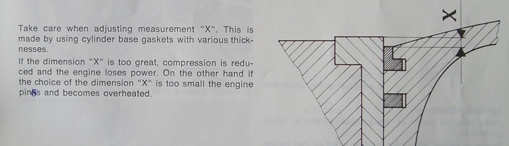
All KTM engines require setting the deck height of the cylinder to establish the proper amount of compression.
The gaskets sets come with an assortment of different thicknesses of base gaskets. Use the proper thickness of base gasket or gaskets to set the deck height "x". NOTE: check the spec sheets for your engine. There is generally 2 specs - one for MC and one for GS. It is recommended that the GS specs be used on 400 engines to make them easier to start.

KTM Clutches
For clutch slippage and sticking the following steps should be followed in order:
-
Check the clutch activator (the bearing plate) on the right side of the motor. Refer to the repair manual for the minimum clearance for the clutch activator arm. If your measurement is less than the minimum (42.5 to 43.5mm between the engine case and the inside curve of the arm) – remove the arm from the actuator and check for wear on the small pin inside the barrel connected to the arm which presses against the clutch rods. If the pin has a flat spot (after 25 years of use, most of these are) replace the pin.
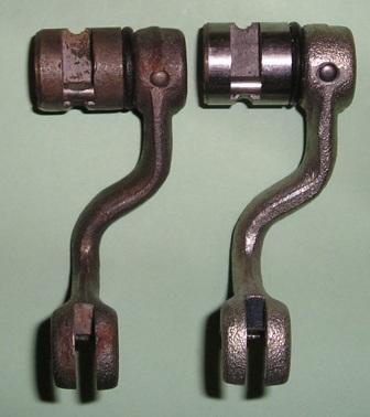
Left photo shows a new clutch arm (right) and a used clutch arm (left)
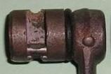
Right photo is an enlargement of the used arm, showing the wear on the top of the pin shown in the center.
-
If the clutch actuator arm is wobbly and loose inside the clutch actuator (it should be a snug fit) replace the clutch actuator (bearing plate) – part #51-32-013-344.
2. The clutch actuator and arm must be within specifications before dis-assembling the clutch. A loose or worn arm assembly will not allow enough pull against the clutch pressure plate to allow the plates to release.
-
Before removing the clutch nuts, observe how many threads are showing through each nut. Remove the clutch plates and check for uneven wear, bent or cupped plates. Hold the plates together in a stack and see if there are any visible gaps between the plates. Replace any plates that are bent or causing gaps.
-
Check all the clutch springs. They must be of the same wire thickness and same length. Check the parts list and repair manual for the spring specifications. Replace any mismatched springs.
-
When re-installing the clutch nuts, they must have uniform pressure when tightened. Check the repair manual for specifications. In most cases, they should not have more than 1-1/2 threads showing above the top of the nuts.
-
Use one continuous safety wire through all of the clutch nuts. You do not have to use individual cotter pins. The purpose of the cotter pins is to prevent the nuts from backing out and reaming a hole through your clutch case.
NOTE: Clutch plates can stick together if the motor has been sitting unused for a length of time (more than 1 month). Although I have not been able to prove it, it is my theory that the type of oil (gear lube) used in the bottom end has an effect on the clutch plates causing them to bond together. Sometimes the plates can be broken loose by starting the engine, pulling the clutch lever in and putting the bike in gear. Or while the bike is moving (at low speed) pull the clutch lever in and apply the brakes.
In worst cases, when a motor has been sitting for 10-20 years, it is best to open the clutch assembly and pry the clutch plates apart.
How to
identify Ceriani and Marzocchi leading axle forks
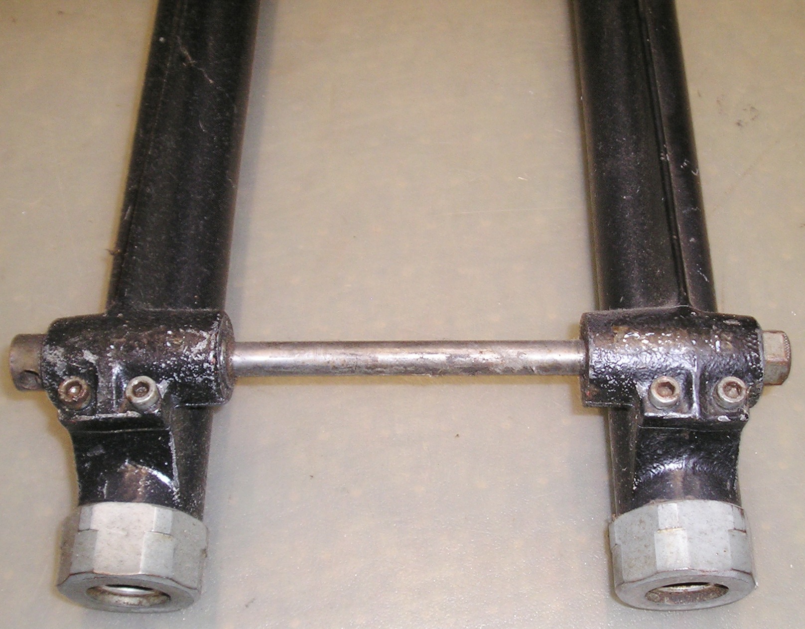
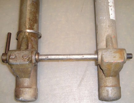
Ceriani bottom legs Marzocchi bottom legs
Above are photos of the Ceriani and Marzocchi leading axle fork legs so that you will be able to tell the difference. The very bottom of the fork legs is the give-away. The Ceriani forks have what look like huge hex nuts on the bottom. These forks legs were painted black. They were after market forks advertised in the Hi-Point catalogs around 1975. These forks take 4 ea 35mm 7mm thick seals (2 per leg).
The Marzocchi bottom fork legs are round and squared off on the inside and outside. These forks were painted grey, orange, or gold.
Both forks are shown in the 1975 (late) Penton parts lists. The Marzocchi 35mm forks came equipped on the 1976+ MC5 bikes and were then equipped on the 1977+ GS6 bikes. In the 1980s the KTM brand bikes came equipped with 38mm, 40mm, or 42mm forks.
Most of the 35 and 38mm Marzocchi forks take two 7mm thick seals in each leg. There are some that take only one 10mm thick seal per leg. The 40mm and 42mm forks take only one 10mm thick seal per leg.
So, the difference would be 14mm or 10mm between the 2 snap rings in each fork leg. It is always best to remove the seal(s) to see how many seals are required. NOTE: Make sure that there is a snap ring above the seal. The wrong size seals are sometimes installed leaving no room to install the snap ring. Example – replacing a 10mm thick seal with two 7mm thick seals – which will cover up the groove for the snap ring.